

- Home
- Request for Quote
- Products
- Variable Frequency Drive Systems and Controls
- AC Variable Frequency Drives
- ABB ACS150 Component Drives :: Overview
- ABB ACS150 Component Drives :: Technical Specifications
- ABB ACS150 Component Drives :: Ratings, Types, Voltages and Construction – Prices
- ABB ACS150 Component Drives :: Dimensions, Weight and Noise
- ABB ACS150 Component Drives :: Interface and Options (prices)
- ABB ACS150 Component Drives :: Technical Data
- ABB ACS150 Component Drives :: Control Connections
- ABB ACS350 General Machinery Drives :: Overview
- ABB ACS350 General Machinery Drives :: Technical Specifications
- ABB ACS350 General Machinery Drives :: Ratings, Types, Voltages and Construction
- ABB ACS350 General Machinery Drives :: Dimensions, Weight and Noise
- ABB ACS350 General Machinery Drives :: Interface and Options (prices)
- ABB ACS350 General Machinery Drives :: Technical Data
- ABB ACS350 General Machinery Drives :: Control Connections
- ABB ACS550 AC Variable Frequency Drive :: Overview
- ABB ACS550 AC Variable Frequency Drive :: Hardware Description
- ABB ACS550 AC Variable Frequency Drive :: Standard Features and Options
- ABB ACS550 AC Variable Frequency Drive :: Specifications
- ABB ACS550 AC Variable Frequency Drive :: 230V Ratings (pricing)
- ABB ACS550 AC Variable Frequency Drive :: 380V Ratings (pricing)
- ABB ACS550 AC Variable Frequency Drive :: 480V Ratings (pricing)
- ABB ACS550 AC Variable Frequency Drive :: Dimensions: ACS550 NEMA 1 R1 through R6 Frame Size
- ABB ACS550 AC Variable Frequency Drive :: Dimensions: ACS550 NEMA 12 R1 through R6 Frame Size
- ABB ACS550 AC Variable Frequency Drive :: Dimensions: ACS550-02 NEMA 1 R7 Frame Size
- ABB ACS550 AC Variable Frequency Drive :: Dimensions: ACS550-02 NEMA 1 R8 Frame Size
- ABB ACS550 AC Variable Frequency Drive :: Dimensions: ACS550-U2 NEMA 1 R7 & R8 Frame Size
- ABB ACS 600 Adjustable Speed AC Drives
- ABB ACS800 AC Variable Frequency Drive :: Overview
- ABB ACS800 AC Variable Frequency Drive :: Standard Features / Available Options and Software
- ABB ACS800 AC Variable Frequency Drive :: Specifications
- ABB ACS800 AC Variable Frequency Drive :: Basic Type Code Information
- ABB ACS800 AC Variable Frequency Drive :: 230V Ratings (pricing)
- ABB ACS800 AC Variable Frequency Drive :: 380V Ratings (pricing)
- ABB ACS800 AC Variable Frequency Drive :: 460V Ratings (pricing)
- ABB ACS800 AC Variable Frequency Drive :: ACS 800-U2 NEMA 1 R7 & R8 Frame Size and ACS 800-02+C111 IP21 (NEMA 1) R7 & R8 Frame Size
- ABB ACS800 AC Variable Frequency Drive :: ACS 800 NEMA 1/12 R2 through R6 Frame Size
- ABB ACS800 AC Variable Frequency Drive :: ACS 800-02 NEMA 1 R7 & R8 Frame Size
- ABB ACS800 AC Variable Frequency Drive :: ACS 800-U4 Module R7 Frame Size
- ABB ACS800 AC Variable Frequency Drive :: ACS 800-U4 Module R8 Frame Size
- ABB ACS880 Industrial Low Voltage AC Drives
- ABB ACS880 AC Drives – Technical Data
- Wall-mounted single drives, ACS880-01
- ABB ACS880 Ratings, types and voltages
- ABB ACS880 AC Drives – Dimensions & Connectivity
- ABB ACS880 AC Drives – Standard Software
- ABB ACS880 AC Drives – Intuitive Human-Machine Interface
- ABB ACS880 AC Drives – Integrated Safety
- ABB ACS880 AC Drives – Flexible Connectivity
- Input/output Modules, Speed Feedback Interfaces & Communication Modules
- ABB Softstarters, Type SSM, Medium Voltage, 2300-13,800V :: Description
- ABB Type SSM Softstarters – Medium Voltage, 2300-13,800V :: General Information
- ABB Type SSM Soft Starters – Medium Voltage, 2300 – 13,800V :: Catalog Numbers
- ABB Soft Starters, Type SSM – Medium Voltage, 2300-13,800V :: Technical Data
- ABB Softstarters, Type SSM, Medium Voltage, 2300-13,800V :: Approx. Dimensions
- Yaskawa AC Drives
- AuCom Soft Starters
- Emerson Industrial Automation (Control Techniques and Saftronics) AC Drives
- Control Techniques – Commander SE AC Drive
- Control Techniques – Commander SK AC Drive
- Commander SK :: Features
- Commander SK :: Terminal Diagram and Description
- Commander SK :: Specifications and Dimensions
- Commander SK – Options :: Overview
- Commander SK – Options :: Configuration and Programming
- Commander SK :: Operator Interface
- Commander SK :: Power Accessories
- Commander SK :: Environmental Protection and Cable Management
- Commander SK :: Input / Output
- Commander SK :: Communication
- Commander SK :: Programming Software
- Control Techniques – Commander SX AC Drive
- Commander SX :: Features, Ratings, Prices and Ordering
- Commander SX :: Terminal Diagram and Description
- Commander SX:: Specifications and Dimensions
- Commander SX :: Options – Overview / Drive Configuration and Programming
- Commander SX :: Communication / Operator Interface
- Commander SX :: Power Accessories
- Commander SX :: Input/Output and Communication
- Control Techniques – Unidrive SP AC Drive
- Unidrive SP :: Features
- Unidrive SP :: Ratings, Prices & Ordering – Wall Mount
- Unidrive SP :: Ratings, Prices & Ordering – Free Standing Cubicle
- Unidrive SP :: Unidrive SP Regen Mode
- Unidrive SP :: Terminal Diagram and Description
- Unidrive SP :: Specifications and Dimensions
- Unidrive SP :: Options – Overview
- Unidrive SP :: Operator Interface
- Unidrive SP :: Power Accessories
- Unidrive SP :: Option & Feedback Modules
- Unidrive SP :: Option Input / Output Modules
- Unidrive SP :: Option Application / Programming Modules
- Unidrive SP :: Option Communication Modules
- Unidrive SP :: Drive Configuration and Programming
- Unidrive SP :: Application Programming Software
- Unidrive SP :: Pre-packaged Solutions
- Saftronics GP10 AC Drives
- Saftronics GP10 – Pricing, Dimensions & Weights
- Saftronics GP10 – Optional DC Link Reactors
- Saftronics GP10 – Options & Accessories
- Saftronics GP10 – Palm Pilot Saflink Kit
- Saftronics GP10 – SR10 Radio Modem Kit
- Saftronics GP10 – Relay Output Card
- Saftronics GP10 – Digital I/O Interface Card
- Saftronics GP10 – Analog I/O Interface Card
- Saftronics GP10 – SF-10 Ethernet Module
- Saftronics GP10 – Interface Option Card
- Saftronics GP10 – Under Torque Detection Option
- Saftronics GP10 – 24 VDC or 24/120 VAC Interface
- Saftronics GP10 – Air Pressure Sensor + V/I Converter Output Card
- Saftronics GP10 – HMI Pump Controller
- Saftronics GP10 – SDBU – Dynamic Brake Module
- Saftronics GP10 – 208-230V Dynamic Brake Packages
- Saftronics GP10 – 460V Dynamic Brake Packages
- Saftronics GP10 – Ratings Efficiency & Watts Loss
- Saftronics GP10 – Standard Specifications
- Saftronics GP10 – Basic Connection Diagram
- Saftronics GP10 – Basic Connection Diagram to PLC
- Saftronics GP10 – Basic Connection Diagram (Europe)
- Saftronics GP10 – Basic Connection to PLC (Europe)
- Saftronics S10 AC Drives
- Saftronics S10 – Options and Accessories
- Saftronics S10 – Standard Specifications
- Saftronics S10 – Dimensions
- Saftronics S10 – Dimensions – Part Number: S102002 – S102003 & S104001 – S104003
- Saftronics S10 – Dimensions – Part Number: S102F25 – S102001
- Saftronics S10 – Dimensions — Part Number: S102F25 – S102001 no Operators
- Saftronics S10 – Dimensions – Part Number: S102002-2003 & S104001-4003
- Saftronics S10 – Basic Wiring Diagram
- Saftronics CV10 AC Drives
- Saftronics CV10 – Part Numbers, Dimensions & Weights
- Saftronics CV10 – LED Keypad with Speed Pot
- Saftronics CV10 – LCD Keypad (supports 5 Languages)
- Saftronics CV10 – Keypad Extension Cable
- Saftronics CV10 – Communication Option Cards
- Saftronics CV10 – Bi-Polar Speed Reference Option Card
- Saftronics CV10 – Standard Specifications
- Saftronics CV10 – Ratings Efficiency and Watts Loss
- Saftronics CV10 – Dimensions Frame 1 – IP20 (Open Chassis)
- Saftronics CV10 – Dimensions Frame 1 – NEMA 1
- Saftronics CV10 – Dimensions Frame 2 – IP20 (Open Chassis)
- Saftronics CV10 – Dimensions Frame 2 – NEMA 1
- Saftronics CV10 – Dimensions Frame 3 – IP20 (Open Chassis)
- Saftronics CV10 – Dimensions Frame 3 – NEMA 1
- Saftronics CV10 – Basic Wiring Diagram
- Saftronics VG10 AC Drive
- Saftronics VG10 – Pricing, Dimensions & Weights
- Saftronics VG10 – Optional DC Link Reactors
- Saftronics VG10 – Options and Accessories
- Saftronics VG10 – Palm Pilot Saflink Kit
- Saftronics VG10 – Relay Output Card
- Saftronics VG10 – SR10 Radio Modem Kit
- Saftronics VG10 – Digital I/O Interface Card
- Saftronics VG10 – Analog I/O Interface Card
- Saftronics VG10 – SF-10 Ethernet Module
- Saftronics VG10 – PGX Encoder Feedback Card
- Saftronics VG10 – Encoder + Analog Output Card
- Saftronics VG10 – PG Feedback Card SOPCG11SPG
- Saftronics VG10 – PG Feedback Card SOPCG11SPG2
- Saftronics VG10 – Synchronized Operation Card
- Saftronics VG10 – 24 VDC or 24/120 VAC Interface Card Kit
- Saftronics VG10 – Air Pressure Sensor + V/I Converter Output Card
- Saftronics VG10 – SDBU – Dynamic Brake Module
- Saftronics VG10 – 208-230V Dynamic Brake Packages
- Saftronics VG10 – 460V Dynamic Brake Packages
- Saftronics VG10 – Ratings Efficiency and Watts Loss
- Saftronics VG10 – Standard Specifications
- Saftronics VG10 – DC Link Reactor 100 HP and Above
- Saftronics VG10 – Basic Connection Diagram (Sink Logic, Mainly America)
- Saftronics VG10 – Basic Connection Diagram to PLC (Sink Logic, Mainly America)
- Saftronics VG10 – Basic Connection Diagram (Source Logic, Mainly Europe)
- Saftronics VG10 – Basic Connection Diagram to PLC (Source Logic, Mainly Europe)
- Saftronics PC10 (Obsolete) AC Drives
- Saftronics PC10 – Options & Accessories
- Saftronics PC10 – SF-10 Ethernet Module Kit
- Saftronics PC10 – 24 VDC or 24/120 VAC Input + Relay Option Card
- Saftronics PC10 – 24 VDC or 24/120 VAC Interface Card Kit (PC10, GP10, or VG10 Inverter)
- Saftronics PC10 – Relay Output Card
- Saftronics PC10 – HMI Pump Controller
- Saftronics PC10 – PC10 120 VAC Option Card
- Saftronics PC10 – Palm Pilot Saflink Kit
- Saftronics PC10 – Dynamic Braking
- Saftronics PC10 – Drive Ratings Efficiency and Watts Loss
- Saftronics PC10 – Standard Specifications
- Saftronics PC10 – Part Number: PC102F12-9, PC102F25-9, PC102F50-9 & PC102001-9
- Saftronics PC10 – Part Number: PC102002-9, PC102003-9, PC104F50-9, PC104001-9, PC104002-9 & PC104003-9
- Saftronics PC10 – Part Number: PC102005-9 & PC104005-9
- Saftronics PC10 – Part Number: PC102007-9, PC102010-9, PC104007-9 & PC104010-9
- Saftronics PC10 – NEMA 1 Kit Dimensions
- Saftronics PC10 – Basic Wiring Diagram
- Fincor 5700 Series (Obsolete) AC Drive
- Fincor 5740 Series (Obsolete) AC Drive
- Fincor 5750 Series (Obsolete) AC Drives
- Motortronics Soft Starters
- SOLCON Soft Starters
- SOLCON RVS-DN Digital Soft Starter with Advanced Motor Protection
- Solcon HRVS-DN Digital Soft Starter with Advanced Motor Protection
- Solcon HRVS-TX Digital Transformer Soft Starter
- SOLCON RVS-AX Analog Soft Starters
- SOLCON Solstart Plus Analog Soft Starters
- SOLCON RVS-BX Basic Soft Starter with Built-In Bypass
- SOLCON RVS-DX Digital Soft Starter with Built-In Bypass
- SOLCON RVS-EX Digital Soft Starter for Explosion Proof motors with Built-In Bypass
- SOLCON SEM-N Rugged Soft Starter for Naval and Military Specifications
- SOLCON SOLSTART Miniature Analogue Soft Starter
- SOLCON SOLSTART 1P Single Phase Analogue Soft Starter
- SOLCON SOLBRAKE DC Injection Brake Soft Starter
- Magnetek – Soft Starters
- WEG Variable Frequency Drives, Controls and Motors
- ABB ACS150 Component Drives :: Overview
- DC Variable Speed Drives
- DC Drive Fundamentals
- ABB DCS 400 Digital DC Converter Drive
- ABB DCS 500 DC Drive
- ABB DCS800 DC Drives Overview
- DCS800 – Power Converter Modules
- DCS800 Panel Drive
- DCS800 Enclosed Converters
- DCS800 Rebuild and Upgrade Kits
- Adaptive Programming and Start-up Assistants
- DriveWindow Light – Startup and Maintenance Tool
- DCS800 Commissioning Macros
- DCS800 Firmware
- DCS800 Technical Specifications
- Current Ratings – Modules – Non-Regenerative
- Current Ratings – Modules – Regenerative
- Current Ratings – Modules – DCS800-EP Panel Drive
- DCS800 Dimensions and Weights
- DCS800 Technical Diagram
- DCS800 Plug-in Options
- DCS800 Feedback Options
- DCS800 Communication Options – Fieldbus Control
- DCS800 External Field Supply
- ABB DCS800-EP replaces Reliance FlexPak® 3000 – 230V Drive Cross Reference
- ABB DCS800-EP – 460V Drive Cross Reference
- ABB DCS800-EP – Options Cross Reference
- ABB DCS800-EP – Product Differences and Remedies – Hardware
- ABB DCS800-EP – Product Differences and Remedies – Control/Interface & Features
- ABB DCS800-EP – Drive Dimensions
- ABB DCS800-EP – Installation Procedure – Wiring and Configuration
- ABB DCS800-EP – Parameter Cross-Reference
- FINCOR Series 2600/2610 DC Drives
- 50 Amp & 90 Amp DC Field Regulators
- Mentor II | Quantum III | FXM5 Change of Status
- SIMOREG 6RA24 Siemens DC Drive Features
- SIMOREG 6RA70 Siemens Variable Speed DC Drive Description and Base Drive Catalog Numbers
- SIMOREG 6RA70 Siemens DC Drive Features
- SIMOREG 6RA70 DC Master Design & Operation – Converters
- SIMOREG 6RA70 Design & Operation – Parameterization Devices
- SIMOREG 6RA70 Design & Operation – Software Structure
- SIMOREG 6RA70 Design & Operation – Closed-Loop Functions in Armature Circuit
- SIMOREG 6RA70 Design & Operation – Closed-Loop in Field Circuit
- SIMOREG 6RA70 Design & Operation – Optimization Run
- SIMOREG 6RA70 Design & Operation – Monitoring & Disgnosis
- SIMOREG 6RA70 Design & Operation – Functions of Inputs & Outputs
- SIMOREG 6RA70 Design & Operation – Safety Shutdown (E-STOP)
- SIMOREG 6RA70 Design & Operation – Serial Interface
- 1000 Hp DC Variable Speed Drive System
- 3000 Hp DC Variable Speed Drive
- Permanent Magnet DC Motors
- SCR Drive Controllers (SCR-Silicon Controlled Rectifier)
- Custom Electric Control Panel Shop
- GE AC & DC Motors (G.E. Motors – General Electric AC & DC Motor)
- GE X$D Ultra® NEMA Premium Efficiency – TEFC AC Motors
- GE Kinamatic® Explosion Proof AC Motors
- GE Energy Saver® – TEFC Severe Duty AC Motors
- GE Kinamatic® General Purpose AC Motors
- GE Motors Energy Saver NEMA Premium Efficiency – ODP AC Motors
- GE ValueLine™ EPAct Efficiency – TEFC AC Motors
- GE ValueLine™ EPAct Efficiency – ODP AC Motors
- GE Permanent Magnet Custom DC Motors
- GE ValueLine™ Vertical Hollow Shaft AC Motors
- GE Permanent Magnet Standard DC Motors
- GE ASD Inverter Duty AC Motors
- G.E. Permanent Magnet Washdown DC Motors
- Avtron – Drives, Measurement and Tachs
- Avtron – Adjustable Speed Drives and Drive Systems
- Avtron – Speed and Length Measurement
- Avtron – Tachs, Tachometers, Encoders, Rotary Pulse Generators
- Avtron – Sales Literature and Instruction Sheets
- Avtron – Classic Tach Models
- Avtron – Price Quotation Request Form
- Avtron – Tachometers Availability
- Avtron – Heavy, Mill-Duty Encoders
- Avtron – Setting Air Gap on M285 Sensors
- Avtron – M4 Universal Encoder
- Avtron – M56, M67, M85 THIN-LINE
- Avtron – M285QUAD Outline Drawing
- Avtron – Severe Duty Encoders
- Avtron – Mill-Duty Encoders
- Avtron – M3 Universal Encoder
- Avtron – M3 Applications
- Avtron – M3 Installation
- Avtron – M3 Specifications
- Avtron – Tach Accessories
- Avtron – Tach Solutions
- Avtron – Rugged Environments
- Avtron – Selection by Motor Frame Size
- Avtron – Adapter Kits Outline Drawings
- Avtron – Motors with Brakes
- Avtron – NEMA C Face Mounting
- Avtron – Market Specific Applications
- Dynapar Encoders and Tachs
- ACURO AI25 Encoders
- Acuro Series AI25 Absolute Encoder with DeviceNet Interface
- Acuro Series AI25 Absolute Encoder with Profibus Interface
- Acuro Series AI25 Absolute Encoder with Interbus Interface
- Acuro Series AI25 Absolute Encoder with BiSS Interface
- Acuto Series AI25 Optical Encoders with SSI Interface
- Acuro Series AI25 Absolute Encoder with Parallel Interface
- Acuro Series AD25 Drive Absolute Encoder
- Series R25 – Mill Duty, HOUSED Resolver
- Series 21/22 Heavy Duty Incremetal Encoders
- Series H20 Encoder
- Series HA25 Dynapar Heavy Duty Encoders
- Series HR25 Incremental Encoders
- Series HC25 Incremental Encoders
- Series H58 Heavy Duty Encoders
- Series H42 Heavy Duty Encoders
- Series HA725 Indusrtial Duty Encoders
- Series HD20 Optical Encoder
- Series HD25 Optical Encoder – Harsh Duty
- Series H56 Rotopulser Heavy Duty Encoders
- RIM Tach 6200 Digital Tachometer
- Series X25 Incremental Encoders
- Series 60 Rotopulser Incremental Encoders
- Series H20 Hub Shaft Encoders
- Series HSD25 Harsh Duty Optical Encoders
- Series HSD44
- Series HS20 Sealed Hollow Shaft Encoders
- Series HS35 Sealed Hollow Shaft Encoders
- The NEW HS35R
- Series HSD35 Shaftless Optical Encoder
- Series HSD37 Hollowshaft Rotary Encoder
- Series HSD38 Harsh Duty Optical Encoder
- Series DWD38 Heavy Duty Rotary Encoders
- SLIM Tach HS56 Incremental Encoder / Tachometer
- RIM Tach HS85 Digital Tachometer
- SLIM Tach SL56 Rotary Encoder
- SLIM Tach RL67 Incremental Rotary Encoder
- SLIM Tach SL85 Digital Tachometer
- SLIM Tach SL1250 Incremental Encoder
- RIM Tach 8500 Digital Tachometer
- RIM Tach 1250 Digital Tachometer
- Series R45 Rotopulser Incremental Encoders
- ACURO AI25 Encoders
- Spare Parts and Replacement Parts
- PLC (Programmable Logic Controllers)
- Services
- Projects
- Operator Stations by Joliet Technologies
- AC VFD, AC Controllers and DC VSD by Joliet Technologies
- Material Handling Modernization Project by Joliet Technologies
- 10 DC (SCR) Drive System :: Neptune Marine Oil & Gas
- Mermaid Offshore Services :: 4 DC (SCR) Drive Cabinets
- “Frontier Driller” Offshore Oil Rig :: DC (SCR) Drive Bays
- 1000Hp Siemens SIMOREG 6RA70 DC Variable Speed Drive Retro-Fit
- Smurfit-Stone: Corrugator Crew Sets Production Record
- Steel Slitting Line for Braner USA
- 1000HP DC Drive, Bow Thruster Application for Pegler Automation
- 1000HP DC Traction Motor Drive, Slurry Pump Application for Baker Hughes
- Siemens 6RA70 DC Drive and GE 752 Traction Motor to Hallett Materials
- ABB ACS 800 VFD to Applied Synergistic
- Two 200Hp Variable Speed DC Drives and Motors to JHT Electronics
- Substrate Technology Inc. :: Joliet Technologies, L.L.C.
- Wyco Tool Company
- Variable Frequency Drives and Controls for Food Processing and Bakery Machinery
- Information
- Guide to Harmonics with AC Variable Frequency Drives
- Variable Speed Drives – Application Information
- Reducing harmonics caused by variable speed drives
- FAQ – Variable Speed Drives Frequently Asked Questions
- EASA Electrical Engineering Handbook
- Part Winding Start
- 3Ph Motors, Single Speed
- 3Ph Motors, 2 Speed, Single Winding
- Connections for NEMA DC Motors
- Connections for NEMA DC Generators
- Field Polarities of DC Machines
- Maximum Locked-Rotor Currents – Three-Phase Squirrel Cage Motors
- NEMA Code Letters for AC Motors
- General Speed-Torque Characteristics
- Effect of Voltage unbalance on Motor Performance
- Starting Characteristics of Squirrel Cage Induction Motors
- Allowable Starts and Starting Intervals
- NEMA Size Starters for Three-Phase Motors
- Starter Enclosures
- NEMA Size Starters for Single-Phase Motors
- Determining the Polarization Index of Machine Windings
- Formulas for Electrical Motors
- Motor Application Formulas
- Glossary of Terms
- Variable Frequency Drive (VFD) Case Studies
- VFD Case Studies – ABB drives & motors help to launch lifeboats quickly and safely.
- VFD Case Studies – Paperboard mill benefits from using DC drives
- VFD Case Studies – ABB Drive cuts water pumping bill for semiconductor plant.
- VFD Case Studies – Insulation manufacturing process saves energy with ABB :: Joliet Technologies
- VFD Case Studies – ABB drives cut costs at MINI production plant
- VFD Case Studies – Film maker slashes costs with ABB drives
- VFD Case Studies – ABB drive cuts costs for wooden toy company
- VFD Case Studies – Close pump control doubles efficiency for West of Scotland Water
- VFD Case Studies – ABB Energy Appraisal Saves Money :: Joliet Technologies
- VFD Case Studies – Staggering energy savings prove value of professional audit
- VFD Case Studies – Soft starters save costs for mechanical engineers
- NEMA Frame Chart and T-Frame Chart :: Joliet Technologies
- Model 1681 Instruction Manual – Firing Circuits DC SCR Drives
- IGBT – Insulated Gate Bipolar Transistors :: Joliet Technologies
- Blog
Blog
What Are the 2026 Top Power Converter Types?
As electrification expands across data centers, electric vehicles, renewable energy, and industrial automation, power converter technology is becoming more specialized. In 2026, the leading designs will not be judged by efficiency alone. Engineers will also examine power density, thermal behavior, control accuracy, service life, and supply-chain stability.
This overview explores the major power converter types shaping current applications. AC-DC converters remain essential inside servers, medical equipment, and household electronics. DC-DC converters regulate battery and renewable-energy voltage with compact switching circuits. DC-AC inverters connect batteries and solar systems to motors or electrical grids. AC-AC converters support motor control, frequency conversion, and industrial heating. Isolated, non-isolated, resonant, and multilevel architectures add further choices.
The “top” category depends on the operating environment. A high-frequency GaN converter may reduce size in a laptop adapter, while a silicon-carbide inverter may handle high voltage inside an electric vehicle. A modular multilevel converter can serve grid-scale systems, but its control design demands careful engineering. Small details matter, including airflow around a heatsink, switching noise near sensors, and connector temperature during peak load.
No single list is universally correct. That distinction is easy to miss. Reliable selection requires verified datasheets, realistic load profiles, thermal testing, and compliance with applicable technical standards. This article compares the strongest candidates for 2026 and considers where each design performs well, where it struggles, and what engineers may still be underestimating. Some forecasts will change. Careful evaluation remains more useful than fashionable terminology.
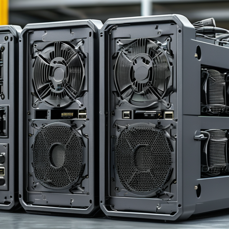
Classify 2026 Power Converters by IEC 60050 Conversion Directions
What Are the 2026 Top Power Converter Types?
Classify 2026 power converters by IEC 60050 conversion directions. AC/DC converters, or rectifiers, turn grid alternating current into stable direct current. They serve data centers, industrial drives, and charging equipment. DC/DC converters adjust one DC voltage to another. They help battery systems deliver controlled power under changing loads. DC/AC converters, commonly called inverters, connect batteries and solar systems to AC networks. AC/AC converters change voltage, frequency, or phase without an intermediate DC link. They remain important in motor control and railway applications.
The label “top” is imperfect. Application decides the ranking. The International Energy Agency reported more than 5 million public electric vehicle charging points worldwide in 2024, in its Global EV Outlook 2025. That expansion increases demand for AC/DC front ends and isolated DC/DC stages. The IEA Renewables 2024 report also forecast nearly 5,500 GW of new renewable capacity from 2024 to 2030. This growth supports larger DC/AC inverter fleets, especially in utility-scale solar and storage.
Bidirectional converters deserve closer attention. They can move energy from a battery to a load, then reverse direction during charging. That flexibility reduces separate hardware, but it complicates control, thermal design, and safety validation. Wide-bandgap semiconductors can improve switching performance, yet their benefits depend on layout and cooling. A converter may look efficient in laboratory conditions and perform differently in a dusty cabinet. Classification clarifies the direction. It does not replace field testing.
What Are the 2026 Top Power Converter Types?
Classified by IEC 60050 conversion directions
IEC 60050 describes power converters by the direction and form of electrical energy conversion: AC to DC rectifiers, DC to AC inverters, AC to AC converters, and DC to DC converters. The chart uses binary technical classification data: 1 indicates that the corresponding AC or DC input/output form is present.
Rank AC–DC Rectifiers by USB PD 3.1’s 240 W Limit and 80 PLUS Ratings
What Are the 2026 Top Power Converter Types?
Rank AC–DC Rectifiers by USB PD 3.1’s 240 W Limit and 80 PLUS Ratings
For a 240 W USB PD 3.1 supply, topology matters more than a promising label. The highest-ranked design is a bridgeless totem-pole rectifier paired with active PFC. It can reduce conduction losses and support excellent efficiency. A well-designed LLC stage then provides isolated, stable output. This architecture suits demanding 48 V, 5 A operation. It also needs careful control and thermal testing.
The second choice is a conventional boost PFC rectifier with an LLC converter and synchronous rectification. It is less adventurous, but easier to validate. Its performance can align with strong 80 PLUS efficiency levels when measured under the correct input and load conditions. Interleaved PFC follows closely. It shares current across phases and can reduce ripple, although its extra components increase cost and failure points. Active-clamp flyback designs are practical for smaller adapters, but they sit below these options near the 240 W ceiling.
Efficiency is not the whole story. Designers should inspect standby power, voltage regulation, ripple, transformer temperature, and protection response. 80 PLUS ratings mainly describe tested power-supply efficiency, not complete USB charger quality. A converter may pass an efficiency target yet produce excessive heat in a compact enclosure. I have seen power estimates look convincing until cable loss and airflow were included. That gap deserves more attention.
Compare Buck, Boost, and LLC DC–DC Stages in 48 V Data-Center Buses
What Are the 2026 Top Power Converter Types?
In 48 V data-center buses, buck, boost, and LLC stages solve different electrical problems.
A buck converter reduces 48 V to lower processor or memory rails. It is compact, fast, and practical for high-current point-of-load conversion. Multiphase buck designs can share heat across several inductors and switches. Still, switching loss rises when current becomes extreme.
A boost converter raises a lower input voltage to a stable bus level. It fits systems with battery droop, long cable losses, or variable renewable inputs. However, boosting a 48 V bus is not always useful downstream. It can add conduction loss and increase electromagnetic interference. Careful testing matters. Measure efficiency across real loads, not one attractive operating point.
An LLC DC–DC stage uses resonant switching and often provides galvanic isolation. It can deliver strong efficiency at high power, especially near its designed load range. Soft switching also reduces switching stress and audible noise. Its weakness is less obvious: wide input and load ranges can complicate regulation. A poorly matched resonant tank may lose efficiency during light-load operation. Engineers should check thermal images, transient response, startup behavior, and fault protection under realistic rack conditions. The best 2026 topology is therefore application-dependent, not simply the newest circuit.
Assess DC–AC Inverters for 800 V EV Platforms and 11 kW Charging
In 2026, the leading power converter types will serve different energy paths. For 800 V EV platforms, DC–AC inverters deserve close attention. They translate battery DC into controlled three-phase AC for traction motors. An effective inverter must handle rapid torque changes without producing excessive heat. Silicon-carbide switches can reduce switching losses, but cooling and circuit layout remain decisive. Small parasitic inductance matters.
At 11 kW, the onboard charger becomes equally important. It converts grid AC into stable battery DC while meeting power-factor and electromagnetic compatibility targets. A three-phase 400 V supply draws roughly 16 A per phase at full output. Engineers should measure efficiency across light, medium, and peak loads. A charger that performs well only at full power is not truly efficient. That mistake is common.
The wider converter set includes isolated DC-DC units for low-voltage systems. They protect control electronics while supplying pumps, lighting, and cabin equipment. Thermal cycling, moisture, vibration, and connector aging require physical validation. Simulation helps, but it cannot reveal every field failure. I would question oversized designs, because extra silicon increases cost, mass, and standby losses. There is no perfect topology. For 800 V systems, insulation monitoring and fault isolation are essential. Reliable results depend on measured data, repeatable tests, and honest review of weak points.
Choose 650 V GaN or 1,200 V SiC Devices by Switching and Power Targets
What Are the 2026 Top Power Converter Types?
Choose 650 V GaN or 1,200 V SiC Devices by Switching and Power Targets
Power converter selection in 2026 will depend less on novelty and more on switching frequency, voltage margin, and cooling limits. A 650 V GaN device suits compact chargers, server power supplies, and high-frequency PFC stages. Its low output charge can reduce switching losses and shrink magnetic components. The Power GaN 2024 report from Yole Group projects strong growth for GaN power devices through the decade, driven by data centers, consumer adapters, and automotive systems.
Fast switching matters here.
A 1,200 V SiC device fits higher-voltage applications, including solar inverters, energy storage, industrial drives, and electric-vehicle powertrains. It offers wider voltage headroom and stronger thermal performance at substantial power levels. The SiC Power Electronics 2024 report from Yole Group identifies traction, renewable energy, and charging infrastructure as major demand areas. The International Energy Agency’s Electricity 2024 report estimates global data-center electricity use could reach 620–1,050 TWh by 2026, increasing pressure on conversion efficiency.
Do not select by voltage alone. A 650 V GaN design may fail its thermal target when switching current rises sharply. A 1,200 V SiC design may add unnecessary cost and gate-drive complexity in a small adapter. Measurements from the real load matter: switching frequency, peak current, isolation, cooling airflow, and transient spikes. My practical concern is simple: efficiency claims often ignore the complete converter. PCB layout, packaging, and control timing can quietly erase impressive device-level results.
What Are the 2026 Top Power Converter Types? — Choose 650 V GaN or 1,200 V SiC Devices by Switching and Power Targets
A practical comparison of converter topologies and wide-bandgap device choices based on voltage, switching frequency, power level, efficiency, and system requirements.
| Converter Type | Typical Input / Output Range | Recommended Semiconductor | Typical Switching-Frequency Range | Practical Power Target | Typical Peak Efficiency Target | Key Strengths | Main Design Limitations | Suitable Applications |
|---|---|---|---|---|---|---|---|---|
| Totem-Pole PFC | 85–264 V AC input; approximately 380–420 V DC bus | 650 V GaN for high-frequency switching legs; silicon or wide-bandgap devices may be used in the line-frequency leg | 65–250 kHz | 300 W–3 kW | 98.0–99.2% | High power density, reduced diode conduction loss, and strong performance at high switching frequency | Requires careful control of dead time, current sensing, electromagnetic-interference filtering, and bridge-leg protection | AC–DC adapters, server power supplies, telecom rectifiers, residential energy systems |
| LLC Resonant Converter | Typically 350–450 V DC input; isolated output from 12 V to 400 V DC | 650 V GaN for compact high-frequency designs; 650 V silicon or silicon carbide may be selected for lower-frequency or higher-temperature designs | 100–500 kHz | 200 W–5 kW | 96.5–99.0% | Soft switching, low switching loss, high power density, and excellent transformer utilization | Performance depends strongly on resonant-tank design; regulation range and light-load operation require careful optimization | Laptop and display adapters, industrial DC supplies, battery chargers, server power modules |
| Phase-Shifted Full Bridge | 350–800 V DC input; isolated output from 24 V to 400 V DC | 650 V GaN for higher-frequency operation; 1,200 V SiC when the DC bus or transient margin exceeds the practical range of 650 V devices | 50–250 kHz | 1–10 kW | 95.5–98.5% | Soft-switching capability, galvanic isolation, and suitability for medium-to-high power | Circulating current and duty-cycle loss can reduce light-load efficiency; transformer leakage inductance must be controlled | Industrial power supplies, welding equipment, telecom rectifiers, battery chargers |
| Interleaved Boost PFC | 85–264 V AC input; approximately 380–420 V DC output | 650 V GaN for compact, high-frequency interleaved phases; silicon carbide can be used when higher voltage margin or ruggedness is required | 50–200 kHz per phase | 1–6 kW | 97.5–99.0% | Lower input-current ripple, reduced magnetic-component size, and easier thermal distribution across phases | More switches, drivers, current sensors, and control complexity than a single-phase boost converter | High-power AC–DC supplies, data-center power shelves, EV auxiliary chargers |
| Bidirectional Dual-Active Bridge | Typically 400–1,000 V DC on the high-voltage side; 24–800 V DC on the low-voltage side | 1,200 V SiC for 800 V-class buses; 650 V GaN for lower-voltage buses and higher-frequency compact systems | 50–300 kHz | 3–30 kW | 95–98.5% | Bidirectional power flow, galvanic isolation, soft-switching potential, and high power density | Wide voltage-ratio operation can create circulating current and loss; modulation and transformer design are critical | Energy storage, vehicle-to-grid systems, isolated DC links, industrial battery systems |
| Three-Phase Two-Level Inverter | 400–800 V DC link; three-phase AC output | 1,200 V SiC for 400–800 V DC links and high transient margin | 8–40 kHz | 5–100 kW | 97–99% | Simple topology, high current capability, and broad compatibility with motor-control and grid-tied systems | Higher switching voltage stress and output-filter requirements than multilevel alternatives; common-mode voltage must be managed | Motor drives, photovoltaic inverters, commercial energy storage, industrial variable-frequency drives |
| Three-Level NPC or T-Type Inverter | 600–1,500 V DC link; three-phase AC output | 1,200 V SiC for medium-voltage DC links and high-efficiency operation | 10–50 kHz | 10–150 kW | 98–99.3% | Lower device voltage stress, improved output waveform quality, and reduced filter requirements | More switches and gate drivers; neutral-point balancing and commutation control increase system complexity | Solar inverters, energy-storage converters, industrial drives, charging infrastructure |
| High-Voltage Buck or Buck-Boost Converter | 400–1,000 V DC input; regulated output from 48 V to 800 V DC | 1,200 V SiC when the input bus approaches 800 V or high-voltage transients are expected; 650 V GaN for sub-650 V buses | 50–300 kHz | 1–20 kW | 96–99% | Efficient DC-link regulation, wide input-voltage range, and suitability for non-isolated power conversion | Does not provide galvanic isolation; switch voltage overshoot, layout inductance, and thermal management require attention | DC fast-charging stages, battery-test equipment, renewable-energy converters, industrial DC buses |
| Flyback Converter | 85–264 V AC or up to approximately 450 V DC input; isolated output below 150 W in common designs | 650 V GaN for high-frequency, compact adapters; silicon devices remain practical at lower switching frequencies | 65–300 kHz | 5–150 W | 85–94% | Low component count, inherent isolation, and economical implementation at low power | Transformer leakage energy, high peak currents, and electromagnetic interference become challenging as power increases | Auxiliary supplies, appliance standby power, small adapters, control electronics |
| Resonant Wireless-Power Converter | Typically 12–400 V DC input; regulated output from 5 V to 400 V DC | 650 V GaN for high-frequency transmitter stages; 1,200 V SiC is generally reserved for higher-voltage industrial links | 85 kHz–1 MHz, depending on the transfer standard and coil design | 10 W–22 kW | 90–97% | Contactless energy transfer, reduced connector wear, and flexible mechanical integration | Efficiency depends on coil alignment, air gap, compensation network, foreign-object detection, and thermal conditions | Consumer wireless charging, automated guided vehicles, robotics, industrial charging platforms |
Related Posts
-
How to Choose the Best AC Converter for Your Electronic Devices
-

Top 10 AC to DC Converter Manufacturers Worldwide?
-

Mastering the Basics of DC Drive Technology for Beginners
-

5 Key Factors Driving the Growth of the Power Converter Market in 2023
-

Understanding How to Convert DC to AC for Your Home Energy Needs
-

How to Choose the Best AC DC Converter Module for Your Project Needs