

- Home
- Request for Quote
- Products
- Variable Frequency Drive Systems and Controls
- AC Variable Frequency Drives
- ABB ACS150 Component Drives :: Overview
- ABB ACS150 Component Drives :: Technical Specifications
- ABB ACS150 Component Drives :: Ratings, Types, Voltages and Construction – Prices
- ABB ACS150 Component Drives :: Dimensions, Weight and Noise
- ABB ACS150 Component Drives :: Interface and Options (prices)
- ABB ACS150 Component Drives :: Technical Data
- ABB ACS150 Component Drives :: Control Connections
- ABB ACS350 General Machinery Drives :: Overview
- ABB ACS350 General Machinery Drives :: Technical Specifications
- ABB ACS350 General Machinery Drives :: Ratings, Types, Voltages and Construction
- ABB ACS350 General Machinery Drives :: Dimensions, Weight and Noise
- ABB ACS350 General Machinery Drives :: Interface and Options (prices)
- ABB ACS350 General Machinery Drives :: Technical Data
- ABB ACS350 General Machinery Drives :: Control Connections
- ABB ACS550 AC Variable Frequency Drive :: Overview
- ABB ACS550 AC Variable Frequency Drive :: Hardware Description
- ABB ACS550 AC Variable Frequency Drive :: Standard Features and Options
- ABB ACS550 AC Variable Frequency Drive :: Specifications
- ABB ACS550 AC Variable Frequency Drive :: 230V Ratings (pricing)
- ABB ACS550 AC Variable Frequency Drive :: 380V Ratings (pricing)
- ABB ACS550 AC Variable Frequency Drive :: 480V Ratings (pricing)
- ABB ACS550 AC Variable Frequency Drive :: Dimensions: ACS550 NEMA 1 R1 through R6 Frame Size
- ABB ACS550 AC Variable Frequency Drive :: Dimensions: ACS550 NEMA 12 R1 through R6 Frame Size
- ABB ACS550 AC Variable Frequency Drive :: Dimensions: ACS550-02 NEMA 1 R7 Frame Size
- ABB ACS550 AC Variable Frequency Drive :: Dimensions: ACS550-02 NEMA 1 R8 Frame Size
- ABB ACS550 AC Variable Frequency Drive :: Dimensions: ACS550-U2 NEMA 1 R7 & R8 Frame Size
- ABB ACS 600 Adjustable Speed AC Drives
- ABB ACS800 AC Variable Frequency Drive :: Overview
- ABB ACS800 AC Variable Frequency Drive :: Standard Features / Available Options and Software
- ABB ACS800 AC Variable Frequency Drive :: Specifications
- ABB ACS800 AC Variable Frequency Drive :: Basic Type Code Information
- ABB ACS800 AC Variable Frequency Drive :: 230V Ratings (pricing)
- ABB ACS800 AC Variable Frequency Drive :: 380V Ratings (pricing)
- ABB ACS800 AC Variable Frequency Drive :: 460V Ratings (pricing)
- ABB ACS800 AC Variable Frequency Drive :: ACS 800-U2 NEMA 1 R7 & R8 Frame Size and ACS 800-02+C111 IP21 (NEMA 1) R7 & R8 Frame Size
- ABB ACS800 AC Variable Frequency Drive :: ACS 800 NEMA 1/12 R2 through R6 Frame Size
- ABB ACS800 AC Variable Frequency Drive :: ACS 800-02 NEMA 1 R7 & R8 Frame Size
- ABB ACS800 AC Variable Frequency Drive :: ACS 800-U4 Module R7 Frame Size
- ABB ACS800 AC Variable Frequency Drive :: ACS 800-U4 Module R8 Frame Size
- ABB ACS880 Industrial Low Voltage AC Drives
- ABB ACS880 AC Drives – Technical Data
- Wall-mounted single drives, ACS880-01
- ABB ACS880 Ratings, types and voltages
- ABB ACS880 AC Drives – Dimensions & Connectivity
- ABB ACS880 AC Drives – Standard Software
- ABB ACS880 AC Drives – Intuitive Human-Machine Interface
- ABB ACS880 AC Drives – Integrated Safety
- ABB ACS880 AC Drives – Flexible Connectivity
- Input/output Modules, Speed Feedback Interfaces & Communication Modules
- ABB Softstarters, Type SSM, Medium Voltage, 2300-13,800V :: Description
- ABB Type SSM Softstarters – Medium Voltage, 2300-13,800V :: General Information
- ABB Type SSM Soft Starters – Medium Voltage, 2300 – 13,800V :: Catalog Numbers
- ABB Soft Starters, Type SSM – Medium Voltage, 2300-13,800V :: Technical Data
- ABB Softstarters, Type SSM, Medium Voltage, 2300-13,800V :: Approx. Dimensions
- Yaskawa AC Drives
- AuCom Soft Starters
- Emerson Industrial Automation (Control Techniques and Saftronics) AC Drives
- Control Techniques – Commander SE AC Drive
- Control Techniques – Commander SK AC Drive
- Commander SK :: Features
- Commander SK :: Terminal Diagram and Description
- Commander SK :: Specifications and Dimensions
- Commander SK – Options :: Overview
- Commander SK – Options :: Configuration and Programming
- Commander SK :: Operator Interface
- Commander SK :: Power Accessories
- Commander SK :: Environmental Protection and Cable Management
- Commander SK :: Input / Output
- Commander SK :: Communication
- Commander SK :: Programming Software
- Control Techniques – Commander SX AC Drive
- Commander SX :: Features, Ratings, Prices and Ordering
- Commander SX :: Terminal Diagram and Description
- Commander SX:: Specifications and Dimensions
- Commander SX :: Options – Overview / Drive Configuration and Programming
- Commander SX :: Communication / Operator Interface
- Commander SX :: Power Accessories
- Commander SX :: Input/Output and Communication
- Control Techniques – Unidrive SP AC Drive
- Unidrive SP :: Features
- Unidrive SP :: Ratings, Prices & Ordering – Wall Mount
- Unidrive SP :: Ratings, Prices & Ordering – Free Standing Cubicle
- Unidrive SP :: Unidrive SP Regen Mode
- Unidrive SP :: Terminal Diagram and Description
- Unidrive SP :: Specifications and Dimensions
- Unidrive SP :: Options – Overview
- Unidrive SP :: Operator Interface
- Unidrive SP :: Power Accessories
- Unidrive SP :: Option & Feedback Modules
- Unidrive SP :: Option Input / Output Modules
- Unidrive SP :: Option Application / Programming Modules
- Unidrive SP :: Option Communication Modules
- Unidrive SP :: Drive Configuration and Programming
- Unidrive SP :: Application Programming Software
- Unidrive SP :: Pre-packaged Solutions
- Saftronics GP10 AC Drives
- Saftronics GP10 – Pricing, Dimensions & Weights
- Saftronics GP10 – Optional DC Link Reactors
- Saftronics GP10 – Options & Accessories
- Saftronics GP10 – Palm Pilot Saflink Kit
- Saftronics GP10 – SR10 Radio Modem Kit
- Saftronics GP10 – Relay Output Card
- Saftronics GP10 – Digital I/O Interface Card
- Saftronics GP10 – Analog I/O Interface Card
- Saftronics GP10 – SF-10 Ethernet Module
- Saftronics GP10 – Interface Option Card
- Saftronics GP10 – Under Torque Detection Option
- Saftronics GP10 – 24 VDC or 24/120 VAC Interface
- Saftronics GP10 – Air Pressure Sensor + V/I Converter Output Card
- Saftronics GP10 – HMI Pump Controller
- Saftronics GP10 – SDBU – Dynamic Brake Module
- Saftronics GP10 – 208-230V Dynamic Brake Packages
- Saftronics GP10 – 460V Dynamic Brake Packages
- Saftronics GP10 – Ratings Efficiency & Watts Loss
- Saftronics GP10 – Standard Specifications
- Saftronics GP10 – Basic Connection Diagram
- Saftronics GP10 – Basic Connection Diagram to PLC
- Saftronics GP10 – Basic Connection Diagram (Europe)
- Saftronics GP10 – Basic Connection to PLC (Europe)
- Saftronics S10 AC Drives
- Saftronics S10 – Options and Accessories
- Saftronics S10 – Standard Specifications
- Saftronics S10 – Dimensions
- Saftronics S10 – Dimensions – Part Number: S102002 – S102003 & S104001 – S104003
- Saftronics S10 – Dimensions – Part Number: S102F25 – S102001
- Saftronics S10 – Dimensions — Part Number: S102F25 – S102001 no Operators
- Saftronics S10 – Dimensions – Part Number: S102002-2003 & S104001-4003
- Saftronics S10 – Basic Wiring Diagram
- Saftronics CV10 AC Drives
- Saftronics CV10 – Part Numbers, Dimensions & Weights
- Saftronics CV10 – LED Keypad with Speed Pot
- Saftronics CV10 – LCD Keypad (supports 5 Languages)
- Saftronics CV10 – Keypad Extension Cable
- Saftronics CV10 – Communication Option Cards
- Saftronics CV10 – Bi-Polar Speed Reference Option Card
- Saftronics CV10 – Standard Specifications
- Saftronics CV10 – Ratings Efficiency and Watts Loss
- Saftronics CV10 – Dimensions Frame 1 – IP20 (Open Chassis)
- Saftronics CV10 – Dimensions Frame 1 – NEMA 1
- Saftronics CV10 – Dimensions Frame 2 – IP20 (Open Chassis)
- Saftronics CV10 – Dimensions Frame 2 – NEMA 1
- Saftronics CV10 – Dimensions Frame 3 – IP20 (Open Chassis)
- Saftronics CV10 – Dimensions Frame 3 – NEMA 1
- Saftronics CV10 – Basic Wiring Diagram
- Saftronics VG10 AC Drive
- Saftronics VG10 – Pricing, Dimensions & Weights
- Saftronics VG10 – Optional DC Link Reactors
- Saftronics VG10 – Options and Accessories
- Saftronics VG10 – Palm Pilot Saflink Kit
- Saftronics VG10 – Relay Output Card
- Saftronics VG10 – SR10 Radio Modem Kit
- Saftronics VG10 – Digital I/O Interface Card
- Saftronics VG10 – Analog I/O Interface Card
- Saftronics VG10 – SF-10 Ethernet Module
- Saftronics VG10 – PGX Encoder Feedback Card
- Saftronics VG10 – Encoder + Analog Output Card
- Saftronics VG10 – PG Feedback Card SOPCG11SPG
- Saftronics VG10 – PG Feedback Card SOPCG11SPG2
- Saftronics VG10 – Synchronized Operation Card
- Saftronics VG10 – 24 VDC or 24/120 VAC Interface Card Kit
- Saftronics VG10 – Air Pressure Sensor + V/I Converter Output Card
- Saftronics VG10 – SDBU – Dynamic Brake Module
- Saftronics VG10 – 208-230V Dynamic Brake Packages
- Saftronics VG10 – 460V Dynamic Brake Packages
- Saftronics VG10 – Ratings Efficiency and Watts Loss
- Saftronics VG10 – Standard Specifications
- Saftronics VG10 – DC Link Reactor 100 HP and Above
- Saftronics VG10 – Basic Connection Diagram (Sink Logic, Mainly America)
- Saftronics VG10 – Basic Connection Diagram to PLC (Sink Logic, Mainly America)
- Saftronics VG10 – Basic Connection Diagram (Source Logic, Mainly Europe)
- Saftronics VG10 – Basic Connection Diagram to PLC (Source Logic, Mainly Europe)
- Saftronics PC10 (Obsolete) AC Drives
- Saftronics PC10 – Options & Accessories
- Saftronics PC10 – SF-10 Ethernet Module Kit
- Saftronics PC10 – 24 VDC or 24/120 VAC Input + Relay Option Card
- Saftronics PC10 – 24 VDC or 24/120 VAC Interface Card Kit (PC10, GP10, or VG10 Inverter)
- Saftronics PC10 – Relay Output Card
- Saftronics PC10 – HMI Pump Controller
- Saftronics PC10 – PC10 120 VAC Option Card
- Saftronics PC10 – Palm Pilot Saflink Kit
- Saftronics PC10 – Dynamic Braking
- Saftronics PC10 – Drive Ratings Efficiency and Watts Loss
- Saftronics PC10 – Standard Specifications
- Saftronics PC10 – Part Number: PC102F12-9, PC102F25-9, PC102F50-9 & PC102001-9
- Saftronics PC10 – Part Number: PC102002-9, PC102003-9, PC104F50-9, PC104001-9, PC104002-9 & PC104003-9
- Saftronics PC10 – Part Number: PC102005-9 & PC104005-9
- Saftronics PC10 – Part Number: PC102007-9, PC102010-9, PC104007-9 & PC104010-9
- Saftronics PC10 – NEMA 1 Kit Dimensions
- Saftronics PC10 – Basic Wiring Diagram
- Fincor 5700 Series (Obsolete) AC Drive
- Fincor 5740 Series (Obsolete) AC Drive
- Fincor 5750 Series (Obsolete) AC Drives
- Motortronics Soft Starters
- SOLCON Soft Starters
- SOLCON RVS-DN Digital Soft Starter with Advanced Motor Protection
- Solcon HRVS-DN Digital Soft Starter with Advanced Motor Protection
- Solcon HRVS-TX Digital Transformer Soft Starter
- SOLCON RVS-AX Analog Soft Starters
- SOLCON Solstart Plus Analog Soft Starters
- SOLCON RVS-BX Basic Soft Starter with Built-In Bypass
- SOLCON RVS-DX Digital Soft Starter with Built-In Bypass
- SOLCON RVS-EX Digital Soft Starter for Explosion Proof motors with Built-In Bypass
- SOLCON SEM-N Rugged Soft Starter for Naval and Military Specifications
- SOLCON SOLSTART Miniature Analogue Soft Starter
- SOLCON SOLSTART 1P Single Phase Analogue Soft Starter
- SOLCON SOLBRAKE DC Injection Brake Soft Starter
- Magnetek – Soft Starters
- WEG Variable Frequency Drives, Controls and Motors
- ABB ACS150 Component Drives :: Overview
- DC Variable Speed Drives
- DC Drive Fundamentals
- ABB DCS 400 Digital DC Converter Drive
- ABB DCS 500 DC Drive
- ABB DCS800 DC Drives Overview
- DCS800 – Power Converter Modules
- DCS800 Panel Drive
- DCS800 Enclosed Converters
- DCS800 Rebuild and Upgrade Kits
- Adaptive Programming and Start-up Assistants
- DriveWindow Light – Startup and Maintenance Tool
- DCS800 Commissioning Macros
- DCS800 Firmware
- DCS800 Technical Specifications
- Current Ratings – Modules – Non-Regenerative
- Current Ratings – Modules – Regenerative
- Current Ratings – Modules – DCS800-EP Panel Drive
- DCS800 Dimensions and Weights
- DCS800 Technical Diagram
- DCS800 Plug-in Options
- DCS800 Feedback Options
- DCS800 Communication Options – Fieldbus Control
- DCS800 External Field Supply
- ABB DCS800-EP replaces Reliance FlexPak® 3000 – 230V Drive Cross Reference
- ABB DCS800-EP – 460V Drive Cross Reference
- ABB DCS800-EP – Options Cross Reference
- ABB DCS800-EP – Product Differences and Remedies – Hardware
- ABB DCS800-EP – Product Differences and Remedies – Control/Interface & Features
- ABB DCS800-EP – Drive Dimensions
- ABB DCS800-EP – Installation Procedure – Wiring and Configuration
- ABB DCS800-EP – Parameter Cross-Reference
- FINCOR Series 2600/2610 DC Drives
- 50 Amp & 90 Amp DC Field Regulators
- Mentor II | Quantum III | FXM5 Change of Status
- SIMOREG 6RA24 Siemens DC Drive Features
- SIMOREG 6RA70 Siemens Variable Speed DC Drive Description and Base Drive Catalog Numbers
- SIMOREG 6RA70 Siemens DC Drive Features
- SIMOREG 6RA70 DC Master Design & Operation – Converters
- SIMOREG 6RA70 Design & Operation – Parameterization Devices
- SIMOREG 6RA70 Design & Operation – Software Structure
- SIMOREG 6RA70 Design & Operation – Closed-Loop Functions in Armature Circuit
- SIMOREG 6RA70 Design & Operation – Closed-Loop in Field Circuit
- SIMOREG 6RA70 Design & Operation – Optimization Run
- SIMOREG 6RA70 Design & Operation – Monitoring & Disgnosis
- SIMOREG 6RA70 Design & Operation – Functions of Inputs & Outputs
- SIMOREG 6RA70 Design & Operation – Safety Shutdown (E-STOP)
- SIMOREG 6RA70 Design & Operation – Serial Interface
- 1000 Hp DC Variable Speed Drive System
- 3000 Hp DC Variable Speed Drive
- Permanent Magnet DC Motors
- SCR Drive Controllers (SCR-Silicon Controlled Rectifier)
- Custom Electric Control Panel Shop
- GE AC & DC Motors (G.E. Motors – General Electric AC & DC Motor)
- GE X$D Ultra® NEMA Premium Efficiency – TEFC AC Motors
- GE Kinamatic® Explosion Proof AC Motors
- GE Energy Saver® – TEFC Severe Duty AC Motors
- GE Kinamatic® General Purpose AC Motors
- GE Motors Energy Saver NEMA Premium Efficiency – ODP AC Motors
- GE ValueLine™ EPAct Efficiency – TEFC AC Motors
- GE ValueLine™ EPAct Efficiency – ODP AC Motors
- GE Permanent Magnet Custom DC Motors
- GE ValueLine™ Vertical Hollow Shaft AC Motors
- GE Permanent Magnet Standard DC Motors
- GE ASD Inverter Duty AC Motors
- G.E. Permanent Magnet Washdown DC Motors
- Avtron – Drives, Measurement and Tachs
- Avtron – Adjustable Speed Drives and Drive Systems
- Avtron – Speed and Length Measurement
- Avtron – Tachs, Tachometers, Encoders, Rotary Pulse Generators
- Avtron – Sales Literature and Instruction Sheets
- Avtron – Classic Tach Models
- Avtron – Price Quotation Request Form
- Avtron – Tachometers Availability
- Avtron – Heavy, Mill-Duty Encoders
- Avtron – Setting Air Gap on M285 Sensors
- Avtron – M4 Universal Encoder
- Avtron – M56, M67, M85 THIN-LINE
- Avtron – M285QUAD Outline Drawing
- Avtron – Severe Duty Encoders
- Avtron – Mill-Duty Encoders
- Avtron – M3 Universal Encoder
- Avtron – M3 Applications
- Avtron – M3 Installation
- Avtron – M3 Specifications
- Avtron – Tach Accessories
- Avtron – Tach Solutions
- Avtron – Rugged Environments
- Avtron – Selection by Motor Frame Size
- Avtron – Adapter Kits Outline Drawings
- Avtron – Motors with Brakes
- Avtron – NEMA C Face Mounting
- Avtron – Market Specific Applications
- Dynapar Encoders and Tachs
- ACURO AI25 Encoders
- Acuro Series AI25 Absolute Encoder with DeviceNet Interface
- Acuro Series AI25 Absolute Encoder with Profibus Interface
- Acuro Series AI25 Absolute Encoder with Interbus Interface
- Acuro Series AI25 Absolute Encoder with BiSS Interface
- Acuto Series AI25 Optical Encoders with SSI Interface
- Acuro Series AI25 Absolute Encoder with Parallel Interface
- Acuro Series AD25 Drive Absolute Encoder
- Series R25 – Mill Duty, HOUSED Resolver
- Series 21/22 Heavy Duty Incremetal Encoders
- Series H20 Encoder
- Series HA25 Dynapar Heavy Duty Encoders
- Series HR25 Incremental Encoders
- Series HC25 Incremental Encoders
- Series H58 Heavy Duty Encoders
- Series H42 Heavy Duty Encoders
- Series HA725 Indusrtial Duty Encoders
- Series HD20 Optical Encoder
- Series HD25 Optical Encoder – Harsh Duty
- Series H56 Rotopulser Heavy Duty Encoders
- RIM Tach 6200 Digital Tachometer
- Series X25 Incremental Encoders
- Series 60 Rotopulser Incremental Encoders
- Series H20 Hub Shaft Encoders
- Series HSD25 Harsh Duty Optical Encoders
- Series HSD44
- Series HS20 Sealed Hollow Shaft Encoders
- Series HS35 Sealed Hollow Shaft Encoders
- The NEW HS35R
- Series HSD35 Shaftless Optical Encoder
- Series HSD37 Hollowshaft Rotary Encoder
- Series HSD38 Harsh Duty Optical Encoder
- Series DWD38 Heavy Duty Rotary Encoders
- SLIM Tach HS56 Incremental Encoder / Tachometer
- RIM Tach HS85 Digital Tachometer
- SLIM Tach SL56 Rotary Encoder
- SLIM Tach RL67 Incremental Rotary Encoder
- SLIM Tach SL85 Digital Tachometer
- SLIM Tach SL1250 Incremental Encoder
- RIM Tach 8500 Digital Tachometer
- RIM Tach 1250 Digital Tachometer
- Series R45 Rotopulser Incremental Encoders
- ACURO AI25 Encoders
- Spare Parts and Replacement Parts
- PLC (Programmable Logic Controllers)
- Services
- Projects
- Operator Stations by Joliet Technologies
- AC VFD, AC Controllers and DC VSD by Joliet Technologies
- Material Handling Modernization Project by Joliet Technologies
- 10 DC (SCR) Drive System :: Neptune Marine Oil & Gas
- Mermaid Offshore Services :: 4 DC (SCR) Drive Cabinets
- “Frontier Driller” Offshore Oil Rig :: DC (SCR) Drive Bays
- 1000Hp Siemens SIMOREG 6RA70 DC Variable Speed Drive Retro-Fit
- Smurfit-Stone: Corrugator Crew Sets Production Record
- Steel Slitting Line for Braner USA
- 1000HP DC Drive, Bow Thruster Application for Pegler Automation
- 1000HP DC Traction Motor Drive, Slurry Pump Application for Baker Hughes
- Siemens 6RA70 DC Drive and GE 752 Traction Motor to Hallett Materials
- ABB ACS 800 VFD to Applied Synergistic
- Two 200Hp Variable Speed DC Drives and Motors to JHT Electronics
- Substrate Technology Inc. :: Joliet Technologies, L.L.C.
- Wyco Tool Company
- Variable Frequency Drives and Controls for Food Processing and Bakery Machinery
- Information
- Guide to Harmonics with AC Variable Frequency Drives
- Variable Speed Drives – Application Information
- Reducing harmonics caused by variable speed drives
- FAQ – Variable Speed Drives Frequently Asked Questions
- EASA Electrical Engineering Handbook
- Part Winding Start
- 3Ph Motors, Single Speed
- 3Ph Motors, 2 Speed, Single Winding
- Connections for NEMA DC Motors
- Connections for NEMA DC Generators
- Field Polarities of DC Machines
- Maximum Locked-Rotor Currents – Three-Phase Squirrel Cage Motors
- NEMA Code Letters for AC Motors
- General Speed-Torque Characteristics
- Effect of Voltage unbalance on Motor Performance
- Starting Characteristics of Squirrel Cage Induction Motors
- Allowable Starts and Starting Intervals
- NEMA Size Starters for Three-Phase Motors
- Starter Enclosures
- NEMA Size Starters for Single-Phase Motors
- Determining the Polarization Index of Machine Windings
- Formulas for Electrical Motors
- Motor Application Formulas
- Glossary of Terms
- Variable Frequency Drive (VFD) Case Studies
- VFD Case Studies – ABB drives & motors help to launch lifeboats quickly and safely.
- VFD Case Studies – Paperboard mill benefits from using DC drives
- VFD Case Studies – ABB Drive cuts water pumping bill for semiconductor plant.
- VFD Case Studies – Insulation manufacturing process saves energy with ABB :: Joliet Technologies
- VFD Case Studies – ABB drives cut costs at MINI production plant
- VFD Case Studies – Film maker slashes costs with ABB drives
- VFD Case Studies – ABB drive cuts costs for wooden toy company
- VFD Case Studies – Close pump control doubles efficiency for West of Scotland Water
- VFD Case Studies – ABB Energy Appraisal Saves Money :: Joliet Technologies
- VFD Case Studies – Staggering energy savings prove value of professional audit
- VFD Case Studies – Soft starters save costs for mechanical engineers
- NEMA Frame Chart and T-Frame Chart :: Joliet Technologies
- Model 1681 Instruction Manual – Firing Circuits DC SCR Drives
- IGBT – Insulated Gate Bipolar Transistors :: Joliet Technologies
- Blog
Blog
What Is a Frequency Drive and How Does It Work?
A frequency drive controls an AC motor by changing the electrical frequency and voltage supplied to it. This sounds simple. Inside the enclosure, a rectifier converts incoming AC power into DC power. A DC link smooths that energy. Then, an inverter uses high-speed switching to recreate AC power at a controlled frequency. Lower frequency usually means lower motor speed. Higher frequency increases speed, within the motor’s safe operating range.
The energy impact is significant. The International Energy Agency’s Energy Efficiency 2023 analysis reports that electric motor systems consume more than 40% of global electricity. The U.S. Department of Energy also identifies motor and drive systems as major industrial energy-saving opportunities. These figures explain why engineers specify frequency drives for pumps, fans, conveyors, compressors, and machine tools. A fan running at reduced speed can avoid throttling losses, while a conveyor can start smoothly instead of pulling a sharp current surge.
Real installations are less tidy. A frequency drive may introduce harmonics, electromagnetic interference, bearing currents, or heat stress. Motor cable length matters. So does grounding. IEC 61800 standards provide a professional framework for adjustable-speed electrical power drive systems, but standards do not replace commissioning judgment. Energy savings are not automatic. Poor parameter settings can reduce efficiency or damage equipment. That is an uncomfortable detail, yet an important one. This guide explains how the technology works, where its benefits come from, and which practical limits deserve careful attention.
What Is a Frequency Drive?
What Is a Frequency Drive?
A frequency drive is an electronic controller for an AC motor. It changes motor speed by adjusting electrical frequency and voltage. Inside, the drive first converts incoming AC power into DC power. A switching inverter then creates a controlled AC output for the motor. This process can make a pump slow down, accelerate smoothly, or hold a stable speed under changing loads.
The impact is substantial. The International Energy Agency’s Energy Efficiency 2017 report estimates that electric motor systems consume about half of global electricity. The U.S. Department of Energy’s Improving Motor and Drive System Performance sourcebook reports that motor systems may use more than 70% of industrial electricity. A frequency drive can reduce waste, especially in fans and pumps, where power demand drops sharply at lower speeds. The savings are not automatic.
Poor programming can increase losses.
In field work, technicians check motor nameplate data, cable length, load behavior, and cooling conditions before commissioning. A drive may reduce mechanical stress by replacing abrupt starts with controlled acceleration. It can also provide fault records, current readings, and overload protection. However, harmonic distortion, electromagnetic interference, and incorrect parameters still require attention. These details are easy to underestimate. Actual energy results depend on operating hours, load profile, and system design, not the drive alone.
The Main Components of a Frequency Drive
What Is a Frequency Drive and How Does It Work?
The Main Components of a Frequency Drive
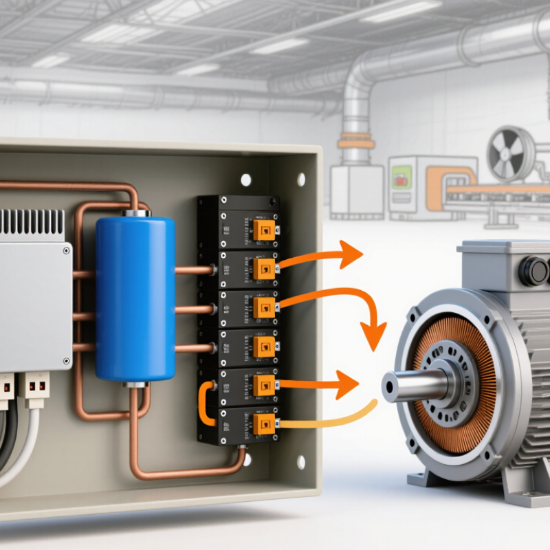
A frequency drive controls an AC motor by adjusting its supplied frequency and voltage. Its internal sections work together like a controlled power pathway. The rectifier receives incoming AC power and converts it into DC power. Diodes or controlled switching devices perform this conversion. The DC link holds this energy temporarily. It usually contains capacitors, and sometimes inductors, to reduce voltage ripple. This stage is easy to overlook. However, poor DC-link performance can create heat, noise, and unstable motor operation.
The inverter changes DC power back into a carefully shaped AC output. Fast electronic switches create this waveform through pulse-width modulation. Changing the pulse pattern changes motor speed and torque. A controller coordinates these switching actions. It reads commands from a keypad, sensor, or external control system. It may also monitor current, voltage, temperature, and motor feedback. In practice, a drive cabinet can feel warm even during normal operation. That is why cooling fans, heat sinks, and ventilation paths matter. Dust on a heat sink can restrict airflow and shorten component life.
Protection circuits watch for overloads, short circuits, excessive temperature, and unusual voltage conditions. A communication interface may connect the drive with a larger control system. One detail I initially underestimated was the importance of wiring. Long motor cables can increase electrical stress and create interference. Shielding, grounding, and correct cable sizing require careful attention. The design is powerful, but not effortless. Configuration errors can still cause rough starts, unexpected trips, or poor energy performance.
What Is a Frequency Drive and How Does It Work? - The Main Components of a Frequency Drive
| Component or Data Dimension | Main Function | Typical Technical Data | How It Works in a Frequency Drive |
|---|---|---|---|
| AC Input | Supplies electrical power to the drive | Common systems use single-phase or three-phase AC; industrial systems frequently use approximately 200–240 V or 380–480 V AC | The incoming AC power is first conditioned and then converted into DC power by the rectifier section. |
| EMI/RFI Filter | Limits conducted electromagnetic interference | May include capacitors, inductors, and common-mode chokes; configuration depends on installation requirements | Reduces high-frequency electrical noise entering or leaving the drive through the power cables. |
| Rectifier Bridge | Converts AC voltage into pulsating DC voltage | A six-pulse diode bridge is widely used in three-phase drives; controlled rectifiers may use active switching devices | The rectifier allows current to flow in a controlled direction so the AC input can supply the DC link. |
| Precharge Circuit | Controls the initial charging current of the DC-link capacitors | Usually consists of a resistor and a relay or contactor; the exact values are design-specific | The resistor limits inrush current during startup, after which a bypass device commonly removes the resistor from the main current path. |
| DC-Link Capacitors | Smooths the rectified voltage and stores energy | Commonly uses electrolytic capacitors; an approximate DC-bus level for a six-pulse drive is 1.35 times the three-phase line-to-line RMS voltage | For example, a 400 V AC three-phase supply can produce a nominal DC bus of roughly 540 V under typical conditions. |
| DC-Link Inductor | Reduces DC-current ripple and limits current disturbances | May be installed internally or externally; inductance and current rating depend on drive size | Works with the capacitors to stabilize the DC link and can help reduce input harmonic current. |
| Inverter Bridge | Converts DC power into variable-frequency AC power | A common three-phase topology uses six power switches, often insulated-gate bipolar transistors or similar semiconductor devices | Rapidly switches the DC bus to synthesize three-phase output voltages with adjustable frequency and amplitude. |
| Power Switching Devices | Performs high-speed electronic switching | Switching frequency is commonly in the range of approximately 2–16 kHz, depending on design, motor, and noise requirements | The switches operate in timed pairs so the motor receives the required phase sequence and voltage pattern. |
| PWM Modulator | Creates the switching pattern for the inverter | Uses pulse-width modulation; space-vector PWM and sinusoidal PWM are common control methods | Changes pulse widths to control the fundamental output voltage, frequency, motor speed, and torque. |
| Control Processor | Executes control algorithms and protection logic | Typically uses a microcontroller, digital signal processor, or combined control platform | Reads commands and feedback, calculates switching signals, manages acceleration and deceleration, and responds to faults. |
| Motor Feedback Interface | Provides motor speed or position information when required | May support an encoder, resolver, or sensorless estimation; basic drives may operate without a physical speed sensor | Feedback improves speed accuracy, torque control, and low-speed performance in closed-loop operation. |
| Current and Voltage Sensors | Measures electrical operating conditions | Commonly uses current transformers, Hall-effect sensors, shunts, or voltage-sensing circuits | The controller uses measurements to regulate torque and detect overcurrent, overvoltage, undervoltage, and phase faults. |
| Braking Chopper and Resistor | Dissipates regenerative energy during rapid deceleration | Optional in many drives; resistor duty and resistance must match the application and drive specifications | When the motor returns energy to the DC link, the chopper directs excess energy to the resistor as heat. |
| Cooling System | Removes heat from semiconductor and passive components | Uses natural convection or forced-air fans; larger systems may use liquid cooling | Maintains component temperatures within their rated limits and helps preserve service life. |
| Motor Output | Delivers adjustable three-phase power to the motor | Output frequency is application-dependent; 0–50 Hz or 0–60 Hz is common for standard motor operation, with higher frequencies possible when permitted by the motor | The drive varies frequency and voltage to control motor speed while maintaining an appropriate volts-per-hertz or vector-control relationship. |
| Protection and Safety Functions | Protects the drive, motor, and personnel | Typical functions include overcurrent, short-circuit, overtemperature, ground-fault, overload, and DC-bus overvoltage protection | The control system monitors operating conditions and can limit output, issue an alarm, or stop the drive when unsafe conditions are detected. |
How a Frequency Drive Controls Motor Speed
What Is a Frequency Drive and How Does It Work?
How a Frequency Drive Controls Motor Speed
A frequency drive controls an AC motor by changing the electrical frequency supplied to its windings. Motor speed follows frequency closely. A 60-hertz supply may produce a faster magnetic field than a 30-hertz supply. The drive first converts incoming AC power into DC power. An inverter then rebuilds that power as controlled AC output.
The process is electronic and precise. Insulated switching devices turn on and off thousands of times per second. Their pulse pattern creates the required voltage and frequency. At low speeds, the drive usually reduces voltage to prevent excessive magnetic flux. This relationship is called volts-per-hertz control. More advanced control methods estimate rotor position and regulate torque with greater accuracy.
Speed changes smoothly.
In real installations, acceleration and deceleration ramps protect couplings, belts, and gearboxes from sudden stress. A current limit can also reduce overheating when a conveyor starts under load. Technicians may add a feedback sensor when the motor must hold speed despite changing resistance. Without feedback, heavy loads can cause small speed errors.
Correct settings matter. An improperly entered motor rating can produce noise, heat, or unstable operation. Cable length, grounding, ventilation, and braking requirements deserve careful attention. I have seen commissioning plans focus on speed control while overlooking cooling at low motor speeds. That is an easy mistake to make. Testing should include unloaded operation, normal load, emergency stopping, and fault response before regular service begins.
What Is a Frequency Drive and How Does It Work?
A frequency drive controls an AC motor’s speed by adjusting the supply frequency. For a four-pole motor, synchronous speed is calculated as n = 120 × f ÷ p. The measured speed is slightly lower because of motor slip under load.
Example: Increasing the frequency from 15 Hz to 60 Hz raises the motor speed from approximately 430 rpm to 1,750 rpm while maintaining a steady voltage-to-frequency ratio.
How Frequency and Voltage Work Together
What Is a Frequency Drive and How Does It Work?
A frequency drive controls an AC motor by changing its frequency and voltage. Frequency sets the motor’s speed. Voltage supports the magnetic field needed to produce torque. They must rise and fall together.
For example, a 50 Hz motor may run near its rated speed at 400 volts. At 25 Hz, the drive commonly supplies about 200 volts. This keeps the volts-per-hertz ratio stable and limits magnetic saturation. If voltage stays too high at low frequency, the motor can overheat. If voltage drops too far, torque may disappear. The simple V/f rule helps, but it is not perfect. Motor temperature, cable length, load inertia, and starting demands also matter.
The International Energy Agency reports that electric motor systems use roughly half of global electricity. That makes proper drive setup an efficiency issue, not merely a controls issue. The U.S. Department of Energy’s pumping-system guidance also highlights the affinity laws: pump power can change approximately with the cube of speed. A small speed reduction may therefore produce a noticeable energy reduction. Real sites can behave differently.
Tips: Check the motor nameplate before programming voltage, current, frequency, and base speed. Measure current under load. Listen for humming or rough acceleration. Those details often reveal poor tuning before a fault appears. A drive that saves energy at one operating point may perform poorly elsewhere. Review the load profile, not just the motor rating.
Common Applications and Benefits of Frequency Drives
A frequency drive controls an AC motor by changing the frequency and voltage supplied to it. Inside the drive, incoming AC power becomes DC power, then an inverter creates a controlled output. This allows the motor to run at the speed a process actually needs. In a workshop, this can mean a conveyor moving gently instead of starting with a sudden jerk.
Frequency drives are common in pumps, fans, compressors, mixers, and HVAC systems. A pump serving a water system can slow down when pressure demand falls. A fan can reduce speed when a room reaches its target temperature. These adjustments often reduce energy use, especially in systems that rarely need full motor speed. Soft starting also lowers mechanical stress and can reduce water hammer in pipelines.
The benefits extend beyond energy savings. Operators gain smoother speed control, fewer abrupt stops, and better process consistency. Drives can also provide fault information, helping technicians investigate overloads, overheating, or abnormal current. In practice, mistakes happen. An incorrectly sized drive may overheat, create electrical interference, or fail to protect the motor properly. Installation should consider cable length, ventilation, load type, and operating conditions. Regular inspection still matters. A drive cannot repair a worn pump, blocked filter, or poorly aligned machine. Its value depends on accurate sizing, careful commissioning, and sensible maintenance.
Related Posts
-
Why Use an AC Drive for Industrial Motors?
-
Top 10 Frequency Drive Suppliers in China for Global Buyers?
-
Top 10 Types of Variable Frequency Drives
-
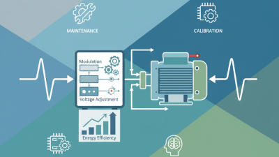
What is a Frequency Drive and How Does it Work?
-

Top 10 Benefits of Variable Speed Drive Motors for Buyers
-
Top 10 Variable Speed Drive Motors for Global Buyers?