

How to Choose the Right DC to DC Voltage Converter?
Choosing the right dc to dc voltage converter begins with the real electrical conditions, not a product label. A converter may accept 24 volts nominally, yet fail when a vehicle system reaches 28 volts during charging. Check the full input range, required output voltage, continuous current, and peak load behavior. A motor, radio, or wireless module can create brief surges that ordinary calculations miss. Measure them when possible.
Efficiency matters, but it is not the only concern. A converter rated at 95% efficiency still releases noticeable heat at higher loads. For example, a 50-watt load can produce several watts of heat inside a small enclosure. That heat needs a path through the circuit board, case, or airflow. Compare regulated and unregulated designs carefully. Review ripple, transient response, isolation, switching frequency, and electromagnetic interference data. A low-cost unit may work on a bench, then disturb a nearby sensor in the finished product. That happened to me once.
Installation details deserve equal attention. Confirm polarity, grounding, wire size, fuse protection, and connector ratings before applying power. Read the manufacturer’s test conditions, because performance figures can change with temperature and load. Look for credible documentation, traceable specifications, and recognized safety testing where applicable. A spreadsheet helps. It does not replace testing. Selecting a converter is an engineering decision shaped by margins, environment, and future demands. Leave room for aging, colder starts, and unexpected load changes. The perfect choice is rarely the smallest or cheapest one. It is the one that remains stable when conditions become inconvenient.
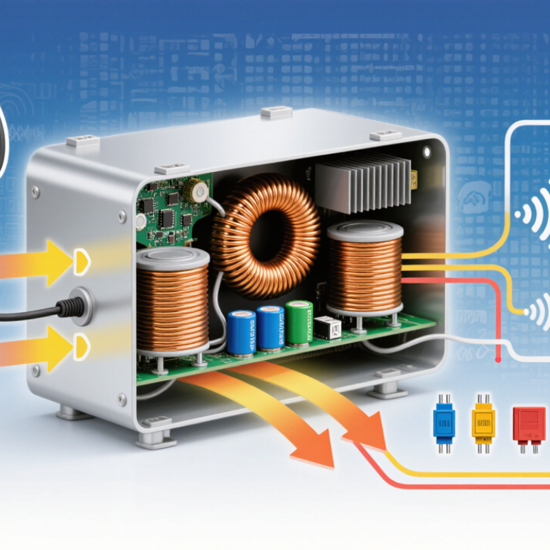
Define the Voltage Conversion Requirements
Choosing a DC to DC voltage converter starts with defining the exact conversion requirements. Record the input voltage range, not only its typical value. Batteries, solar systems, and vehicle supplies can fluctuate significantly.
Specify the required output voltage and allowable tolerance. Then calculate the continuous current and the highest temporary load. Motors, wireless transmitters, and processors may create sudden demand. Measure the load. Do not guess. Output ripple also matters, especially in audio, sensing, and communication circuits. A converter that meets voltage requirements may still introduce unwanted electrical noise.
Efficiency affects heat, battery life, and enclosure size. Compare efficiency across the real operating range, rather than trusting one headline figure. Check startup behavior, short-circuit protection, thermal limits, and switching frequency. Isolation may be necessary when different circuits must remain electrically separated. In practical testing, I use an electronic load and oscilloscope to observe voltage dips during fast load changes. A neat spreadsheet can still mislead. Wiring resistance, connector losses, and airflow often change the result. Leave reasonable margin for aging and temperature variation. The smallest converter is not always the most dependable choice. Sometimes, a slightly larger unit provides steadier performance and simpler thermal management. Record every assumption before selecting the final electrical specifications.
| Requirement | What to Define | Practical Design Target | Why It Matters |
|---|---|---|---|
| Input Voltage | Nominal, minimum, maximum, and transient input voltage | Converter input range should cover the full operating range, including battery or supply tolerances | A converter rated only for nominal voltage may shut down or suffer damage during low-voltage conditions, charging, or input surges. |
| Output Voltage | Required regulated output voltage and allowable tolerance | Select a fixed or adjustable output with regulation appropriate to the load; common regulated rails include 3.3 V, 5 V, 12 V, 15 V, and 24 V | Digital ICs, sensors, communication circuits, and motors can have different voltage limits and startup requirements. |
| Output Current | Continuous current, peak current, startup current, and inrush current | Choose a continuous current rating at least 20% to 30% above the calculated maximum load when thermal conditions permit | Additional margin helps prevent overheating, current-limit activation, and output-voltage drop during load changes. |
| Output Power | Maximum load power calculated as output voltage multiplied by output current | POUT = VOUT × IOUT; select a converter with a power rating above the calculated requirement | Power capability determines the usable load range and affects package size, cooling, and efficiency. |
| Conversion Direction | Whether the output must be higher, lower, or either higher or lower than the input | Use a buck converter for step-down, a boost converter for step-up, and a buck-boost converter when the input can cross the required output voltage | The correct topology improves regulation, efficiency, and operating stability. |
| Isolation | Whether galvanic isolation is required between input and output | Specify an isolated converter when safety separation, ground-loop prevention, or independent circuit domains are required | Non-isolated converters are usually smaller and more efficient, while isolated designs provide electrical separation but require additional design considerations. |
| Efficiency | Minimum acceptable efficiency at typical and maximum load | Compare efficiency across the actual operating range rather than relying only on the peak efficiency value | Efficiency affects input current, battery runtime, heat generation, and enclosure temperature. |
| Thermal Conditions | Ambient temperature, airflow, enclosure size, mounting method, and allowable component temperature | Verify the converter’s derating curve and provide adequate PCB copper area, airflow, or heatsinking where necessary | Rated power commonly decreases as ambient temperature rises, especially in compact or sealed equipment. |
| Output Ripple and Noise | Maximum permissible periodic ripple and broadband noise at the output | Choose ripple performance compatible with the load; sensitive analog, RF, and measurement circuits may require additional filtering or a post-regulator | Excessive ripple can affect signal accuracy, audio performance, communications, and processor stability. |
| Transient Response | Allowable output deviation during load steps and input changes | Check measured transient response with the intended output capacitance, load range, and layout conditions | Fast load changes can cause temporary voltage dips or overshoot even when steady-state regulation is within specification. |
| Protection Functions | Overcurrent, short-circuit, overvoltage, overtemperature, input undervoltage, and reverse-polarity protection | Select protection features based on the failure modes and safety requirements of the end product | Protection can reduce damage during wiring errors, blocked loads, abnormal temperatures, and system faults. |
| Startup Behavior | Soft-start time, enable control, power-good indication, and startup into a pre-biased output | Confirm that startup timing and sequencing match the requirements of the system controller and downstream loads | Controlled startup limits inrush current and helps prevent reset failures or incorrect power sequencing. |
| Input Current | Expected input current under normal operation and worst-case load | Estimate IIN ≈ POUT ÷ (VIN × efficiency), then verify the source and wiring can support it | Low input voltage and high output power can produce substantial input current, requiring suitable connectors, fuses, and conductors. |
| EMI and Layout | Conducted and radiated emissions limits, switching frequency, cable length, and PCB layout constraints | Follow the recommended layout, minimize high-current loop areas, and plan input/output filtering early | Switching converters generate high-frequency energy that can interfere with nearby sensors, radios, clocks, and control circuits. |
| Environmental Requirements | Operating temperature, humidity, vibration, shock, altitude, and moisture exposure | Choose a converter whose environmental ratings exceed the actual application conditions | Electrical performance and service life can change significantly in high humidity, vibration, extreme temperatures, or reduced air pressure. |
| Regulatory and Safety | Required creepage, clearance, insulation, dielectric withstand, and electromagnetic compatibility criteria | Define applicable product-level safety and EMC requirements before finalizing the converter architecture | Compliance depends on the complete assembly, including the PCB, enclosure, wiring, shielding, and external components. |
Related Posts
-
Best DC Converter Types Explained What You Need to Know?
-
2026 Top DC to DC Voltage Converter Solutions for Global Buyers?
-
What Are the 2026 Top Power Converter Types?
-

How to Choose the Best DC to AC Converter for Your Needs?
-

Understanding the Differences Between AC to DC Inverters for Your Power Needs
-

Top 10 DC Motor Controller Options for Global Buyers?